vibration criteria

Determining lab building vibration criteria: consequences vs. interference

Determining lab building vibration criteria: consequences vs. interference

There’s an art to developing floor vibration criteria, and the complexity increases when there aren’t explicit limits given to us by tool vendors. Even when those vendor-supplied instrument criteria are available and realistic, we need to think about what those criteria mean and how aggressively we should view risks to the project. 

Bright-line vibration and noise criteria

Bright-line vibration and noise criteria

If you’re outfitting a low-vibration imaging suite or laboratory, you’ve probably had to read a few tool installation guides for off-the-shelf (as opposed to hand-built) instruments. These documents are provided by instrument vendors and provide some environmental guidelines for parameters like floor vibration, acoustical noise, EMI, temperature, humidity, and more.

Upcoming paper: statistical descriptors in the use of vibration critiera

If you are a member of IEST and have some interest in low-vibration environments in research settings, I will encourage you to sit in on a session on "Nanotechnology Case Studies" at ESTECH. I'll be presenting some work on the statistical methodologies that we have been developing over time. I know of at least three other presentations, and they all look intriguing. So, I hope that this will be well-attended. See the abstract for my paper below.

"Nanotechnology Case Studies", ESTECH 2017, May 10 from 8AM to 10AM

Consideration of Statistical Descriptors in the Application of Vibration Criteria

Byron Davis, Vibrasure

Abstract:

Vibration is a significant “energy contaminant” in many manufacturing and research settings, and considerable effort has been put into developing generic and tool-specific criteria. It is important that data be developed and interpreted in a way that is consistent with these criteria. However, the criteria do not usually include much discussion of timescale or an appropriate statistical metric to use in determining compliance. Therefore, this dimension in interpretation is often neglected.

This leads to confusion, since two objectively different environments might superficially appear to meet the same criterion. Worse, this can lead to mis-design or mis-estimation of risk. For example, a tool vendor might publish a tighter-than-necessary criterion simply because an “averaging-oriented” dataset masks the influence of transients that are the actual source of interference. On the other hand, unnecessary risk may be encountered due to lack of information regarding low- (but not zero-) probability conditions or failure to appreciate the timescales of sensitivities. 

In this presentation, we explore some of the ways that important temporal components to vibration environments might be captured and evaluated. We propose a framework for data collection and interpretation with respect to vibration criteria. The goal is to provide a language to facilitate deeper and more-meaningful discussions amongst practitioners, users, and toolmakers. 
 

How to Read Centile Statistical Vibration Data

I recently wrote about timescales and temporal variability in vibration environments

In that post, and in a related talk I gave at ESTECH, I presented a set of data broken down statistically. That is to say, I took long-term monitoring data and calculated centile statistics for the period. This plot illustrates how often various vibration levels might be expected. Here's an example:

The above data illustrate the likelihood of encountering different vibration levels in a laboratory. Each underlying data point is a 30-second linear average. In this case, the statistics are based on 960 observations over the course of 480 minutes …

The above data illustrate the likelihood of encountering different vibration levels in a laboratory. Each underlying data point is a 30-second linear average. In this case, the statistics are based on 960 observations over the course of 480 minutes between 9AM and 5PM. 

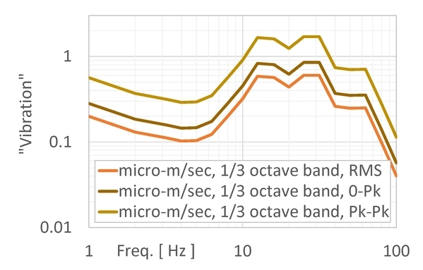
Like spatial statistics, temporal statistics are based on multiple observations. Unlike spatial statistics, however, far more data points may be collected. Considerably greater detail is available, and you can generate representations far more finely-grained than "min-max" ranges or averages.

For field or building-wide surveys, our practice is to supplement the spatial data gathered across the site with data from (at least) one location gathered over time. This really helps illustrate how much of the observed variability in the spatial data might actually be due to temporal variability. If vibrations from mechanical systems are present, and if they cycle on and off (like an air compressor), then it also helps you see those impacts.

But interpreting these data isn't intuitive for some people. So, I figured it would be helpful to explain a little bit about how to look at centile statistical vibration data. Returning to the example above: Each Ln curve illustrates the vibration level exceeded n% of the time. This is calculated for each frequency point in the spectrum. In other words, the L10 spectrum isn't the spectrum that was exceeded 10% of the time. Instead, the L10 spectrum shows the level that was exceeded at each individual frequency 10% of the time.

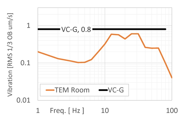
One of the most striking features of centile statistical data is the presence of "bulges" and "pinches". The large bulge between 8 and 10Hz is indicative of a very wide range of vibration levels at this frequency – the distribution is skewed, such that higher vibration levels are more likely than at other frequencies. The pinch at 63Hz indicates that the range of vibration levels has collapsed, perhaps due to the dominance of near-constant vibrations emitted by a continuously-operating nearby machine.

The figure may be read to say that, for a typical work day on the 30-sec timescale, this particular environment meets VC-D/E 99.7% of the time; VC-E 99% of the time; and VC-E/F 95% of the time. There are other interpretations, but this is the most straightforward way to think about it.

Of course, your input data (the monitoring period) has to be representative. If you do a 24-hour measurement, then the statistics won't make perfect sense in a lab that operates 9~5. And if you are looking for rare events, then you'd better collect enough data to be able to make credible statements about those rare events. 

A quick note regarding vibration and noise units

Just a quick note regarding expressions of vibration and acoustical data. Every now and then we come upon a vexing problem related to full expressions of the units of a measurement (or criterion).

I'm not talking about gross errors, like confusion of "inches-vs-centimeters" or "pounds-vs-newtons". Instead, I'm referring to some of the other, more subtle parts of the expression, like scaling and bandwidth.

Take a look at the plots below; this is from a vibration measurement in a university electron microscopy suite. Note that all of the data shown in this blog post are completely identical; however, they are expressed in different terms. I've re-cast this same singular spectrum in different terms so that you can see how much it matters to have a full expression of the units we're talking about.

To start, we surely won't confuse big-picture terms, like the difference between acceleration, velocity, and displacement. Which one you work with doesn't matter much, but we'd better be sure we understand the difference between them:

Data above are from a single measurement, expressed in acceleration, velocity, and displacement. Obviously, these units are all different, so the curves look different, despite the fact that each spectrum relates exactly the same information.

Data above are from a single measurement, expressed in acceleration, velocity, and displacement. Obviously, these units are all different, so the curves look different, despite the fact that each spectrum relates exactly the same information.

Also, we probably won't get fooled by the physical units, like inches-vs-meters. At the very least, we have a good "order-of-magnitude" sense of where things ought to land; if you have an electron microscopy suite with vibrations in double-digits, then they'd better be micro-inches/sec (rather than micro-meters/sec), or else you're in trouble:

The same data from before, now expressed using two different sets of units of velocity. Obviously, if you have a criterion like "0.8um/sec" then you'd better compare against the curve expressed in um/sec rather than the one in uin/sec. But…

The same data from before, now expressed using two different sets of units of velocity. Obviously, if you have a criterion like "0.8um/sec" then you'd better compare against the curve expressed in um/sec rather than the one in uin/sec. But are we finished? Do we have a complete expression of the "units" yet?

We're not quite finished, though. Just because we've agreed on terms (velocity) and physical units (micro-meters/sec), we still have some work to do. We never said what the measurement bandwidth should be. We've been showing narrowband data, but what if the criterion is expressed in some other bandwidth? Maybe it's not even a constant bandwidth, but rather a proportional bandwidth, like (commonly-used) 1/3 octave bands:

This is still all the same data, only we are now showing it in narrowband (1Hz bandwidth) as well as in 1/3 octave bands. Note that widths of the 1/3 octave bands scale with frequency as f*0.23, so at low frequencies (below 4Hz) the 1/3 octave band …

This is still all the same data, only we are now showing it in narrowband (1Hz bandwidth) as well as in 1/3 octave bands. Note that widths of the 1/3 octave bands scale with frequency as f*0.23, so at low frequencies (below 4Hz) the 1/3 octave band is actually smaller than 1Hz.

OK, so now we have terms (velocity), physical units (micro-m/sec), and bandwidth (let's choose 1/3 octave band). But we're still not quite finished: we still need to say what signal scaling we're using. You might have seen this referred to using phrases like "RMS" or "Peak-to-Peak":

Again, these are the same data as above, but now we've chosen the 1/3 octave band velocity in micro-m/sec. But if we're supposed to compare against a criterion, which scaling do we use? There's a big difference between the RMS, zero-to-peak, and pea…

Again, these are the same data as above, but now we've chosen the 1/3 octave band velocity in micro-m/sec. But if we're supposed to compare against a criterion, which scaling do we use? There's a big difference between the RMS, zero-to-peak, and peak-to-peak values. 

If I told you that the limit was 0.8um/sec, then would you say that this room passes the test? As you might surmise, you can't answer that question if all I told you that the limit was 0.8um/sec. You need to know exactly what I mean by "0.8um/sec". I know it sounds funny, but just plain micro-meters-per-second is not a complete expression. You have to tell me whether we're talking 0.8um/sec RMS; or zero-to-peak; or peak-to-peak. You'll also have to tell me what bandwidth you want: PSD? 1/3 Octave Band? Narrowband, with some specific bandwidth? 

If you were to tell me that you need to meet 0.8um/sec RMS in 1/3 octave bands, then we can plot the data appropriately and make some intelligent statements:

Since we've been given a full expression of the criterion (0.8um/sec RMS in 1/3 octave bands, which happens to be IEST's VC-G curve), we can plot the data with those units and overlay the criterion. This room passes the test, but without a full expr…

Since we've been given a full expression of the criterion (0.8um/sec RMS in 1/3 octave bands, which happens to be IEST's VC-G curve), we can plot the data with those units and overlay the criterion. This room passes the test, but without a full expression, we couldn't say one way or the other.

We see this kind of problem all the time. Most notably, we see people comparing narrowband measurement data against a 1/3 octave band criterion like those in the VC curves. This is just plain wrong, because the measurement and criterion are literally expressed in different units. The VC-G criterion isn't simply "0.8um/sec"; instead, it is actually "0.8um/sec RMS in 1/3 octave bands from 1 to 80Hz". 

This is important, and it matters a lot!